Mk II: custom PCB (proposal)
Status: design proposal, seeking sponsorship
Mk II is specified from the simulation studies below; the schematic capture and layout start once parts and board fabrication are funded. Sponsor it.
Mk I proves the software. Mk II removes the four hardware limits the simulator keeps running into: slow wall sensing, a body laid out without regard to yaw inertia, a consumer gyro and blind motors. The board is the chassis, as on competitive micromice: motors, sensors and battery mount directly to a 4-layer PCB.
What the studies predict
Each line item is justified by a simulation study (design studies), not by habit:
| Upgrade | Mk I | Mk II | Predicted effect (simulation) |
|---|---|---|---|
| Wall sensing | VL53L0X ToF, 30 Hz, about 3 mm noise | 4 to 6 pulsed IR pairs, 1 kHz, about 1 mm | smooth runs: path error −30 % (3.2 → 2.2 mm RMS, worst case 6.6 → 4.6 mm); diagonals: no change until post-based correction is added (M5), which the 1 kHz rate makes possible (sensor study) |
| Chassis | 95 × 80 mm, modules on a plate, radius of gyration about 35 mm | 64 to 72 mm PCB chassis, battery over the axle, wheels as far apart as the body allows | turns are capped by angular acceleration, and the grip limit on it is \(\alpha_{grip} = b\sqrt{(\mu g)^2 - a_{lat}^2}/2k^2\): it grows with \(1/k^2\) and does not depend on mass. 80 instead of 60 rad/s² makes smooth runs 11 % faster (angular-acceleration study). Width alone changes the run time by under 1 % but gives the same turns up to 8 mm more clearance (width study) |
| Gyro | MPU6050, ±3 % scale, large thermal drift | ICM-42688-P, ±0.5 % scale, low noise and drift | diagonals hold at 28 to 30 of 32 runs with the scale within ±0.15 % and fall to 20 of 32 at ±0.3 % (gyro study); lower thermal drift keeps a calibration valid through a contest day |
| Motor sensing | none | low-side current sense on both motors | torque and traction-loss estimate; crash detection without waiting for a position error |
Block diagram
flowchart LR
  BAT["2S LiPo 300-450 mAh"] --> RP["reverse-polarity<br/>P-MOSFET"]
  RP --> VM["motor rail VBAT"]
  RP --> BUCK["TPS62162<br/>buck 3.3 V, 1 A"]
  RP --> DIV["battery<br/>divider"]
  BUCK --> S3["ESP32-S3-WROOM-1<br/>2 x LX7 240 MHz<br/>native USB"]
  VM --> DRV["DRV8835<br/>dual H-bridge"]
  S3 -->|"MCPWM"| DRV
  DRV --> M((motors +<br/>magnetic encoders))
  M -->|"PCNT"| S3
  DRV --> CS["INA180 x2<br/>current sense"]
  CS -->|ADC2| S3
  S3 -->|"LED_EN x6"| IRE["IR emitters<br/>SFH 4545"]
  IRR["IR receivers<br/>TEFT4300"] -->|"ADC1"| S3
  IMU["ICM-42688-P<br/>SPI 24 MHz"] --> S3
  USB["USB-C<br/>flash + log"] --> S3
IR wall sensor: one channel
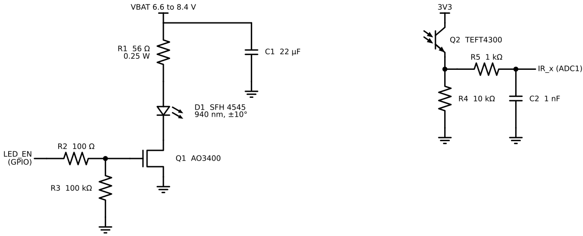
Drawn by hardware/v2/ir_frontend.py. Each channel pulses an IR LED and reads a phototransistor twice, once dark and once lit; the difference rejects ambient light.
Emitter
The LED is pulsed from the battery rail through R1 by a logic-level MOSFET. With the SFH 4545 forward voltage \(V_F \approx 1.5\) V and a target pulse current of 100 mA at the nominal 7.4 V:
Over the battery range the pulse current is
Each LED is on for at most \(t_p = 40\ \mu s\) per 1 ms frame (\(D = 4\,\%\)), so the average LED current is under 5 mA and the average resistor dissipation
well inside a 0.25 W part. The peak exceeds the LED's 100 mA DC rating only in short, low-duty pulses, which is how these emitters are rated to be driven; the exact pulse rating is checked against the datasheet at schematic capture. Because the light output is proportional to \(I_F\), every reading is normalised by \((V_{BAT} - V_F) / (7.4 - V_F)\) using the battery voltage the firmware already measures.
The AO3400 switches fully at 3.3 V gate drive (\(R_{DS(on)} < 50\) mΩ at \(V_{GS} = 2.5\) V, so \(V_{DS} \approx 6\) mV). With \(R_2 = 100\ \Omega\) and an input capacitance around 600 pF the gate time constant is about 60 ns, negligible next to the 40 µs pulse. \(R_3\) holds the LED off while the ESP32 boots. The 22 µF reservoir supplies the pulse locally: the 4.9 µC per pulse sags it by \(\Delta V = Q / C \approx 0.22\) V, and the battery recharges it between pulses.
Receiver
The phototransistor works as an emitter follower: \(V_{out} = I_{ph} R_4\). It saturates when \(V_{out}\) approaches \(3.3\ \text{V} - V_{CE(sat)}\), so
\(R_4\) is the channel's gain: it is chosen on the bench so that the closest wall the robot can see (about 25 mm) stays below saturation, with 4.7 k and 22 k footprints as alternatives. A larger \(R_4\) also slows the phototransistor, so the sampling instant inside the pulse is set from the measured settling time. \(R_5 C_2\) (\(\tau = 1\ \mu s\), \(f_c = 160\) kHz) is the anti-alias filter and charge reservoir for the ADC's sampling capacitor.
Reading distance
For a diffuse wall the received signal falls roughly with the square of the distance:
\(a\) and \(d_0\) are fitted per channel from a few known distances (the existing ToF calibration mode, extended to five points). Noise in \(s\) maps to distance as
so resolution is best exactly where it matters, close to the walls. The simulator's IR model assumes 1 mm noise at wall distances, which is conservative for a 12-bit converter at these signal levels.
Timing
A hardware timer at 4 kHz serves one channel per tick (dark read, LED on, settle, lit read, LED off), so each of four channels is read at 1 kHz, synchronous with the control loop. Six channels fit at 6 kHz.
Parts
| Block | Part | Why this part |
|---|---|---|
| MCU | ESP32-S3-WROOM-1 | Two cores like Mk I (same task split); native USB for flashing and logs; MCPWM with dead time for the bridge; PCNT for encoders |
| IMU | ICM-42688-P | lower gyro noise and much lower temperature drift than the MPU6050; sensitivity tolerance about ±0.5 % instead of ±3 % before calibration |
| Bridge | DRV8835 | two channels, 1.5 A each, 11 V max: right for 2S, and tiny (2 × 2 mm) |
| Current sense | INA180A2 + 50 mΩ low-side shunt per motor | 0 to 1.3 A into the ADC: motor torque, slip and stall detection |
| 3.3 V | TPS62162 synchronous buck | 3 to 17 V in, 1 A, about 90 % efficient instead of a linear drop from 7.4 V |
| IR | SFH 4545 + TEFT4300, 4 to 6 pairs | narrow-beam 940 nm emitter, matched phototransistor |
| Motors | micro metal gearmotor with magnetic encoder (budget) or coreless with integrated encoder (performance) | coreless motors have far lower rotor inertia: faster torque response |
| Board | 4 layers, 1.6 mm: signal / GND / power / signal | unbroken ground under the analogue IR traces, motor currents kept on their own copper |
Budget
Single-unit 2026 distributor prices, rounded; to be replaced by real quotes.
| Item | Budget build (USD) | Performance build (USD) |
|---|---|---|
| ESP32-S3 module, IMU, bridge, current sense, buck, passives, connectors | 30 | 30 |
| IR emitters and receivers (6 pairs plus spares) | 15 | 15 |
| Motors with encoders (pair) | 30 | 120 to 200 |
| Wheels, tyres, bearings, hardware | 15 | 30 |
| Batteries (2 × 2S) and charger share | 25 | 25 |
| PCB fabrication + assembly, 5 boards, 4 layers | 80 | 120 |
| Robot | about 195 | about 340 to 420 |
| Practice maze section (6 × 6 cells, MDF, painted) | 150 | 150 |
The spending plan and what sponsors get are on the sponsor page.
Bring-up plan for Mk II
- Power and USB: rails within 2 %, current draw idle, reverse-polarity test.
- IMU over SPI at full rate; noise and bias measured still for 10 minutes, at two temperatures.
- IR channels: dark/lit levels, saturation margin at 25 mm, settling time on a scope, calibration fit residuals.
- Motors and current sense: no-load speed and current, stall current, \(k\) and \(R\) from the data (updating the model in
config.h). - Then the Mk I bring-up plan from step 4, with the flight log compared against the simulator after every run.