Current robot (Mk I)
The first hardware is deliberately built from modules: an ESP32 DevKit, breakout boards and N20 gear motors on a perfboard or simple carrier. Everything is cheap, easy to replace, and good enough to validate the software. The custom PCB proposal is the step after it.
flowchart LR
  BAT["2S LiPo<br/>7.4 V"] --> F["PTC fuse<br/>+ switch"]
  F --> DRV["TB6612FNG<br/>dual H-bridge"]
  F --> BUCK["MP1584<br/>buck 5 V"]
  F --> DIV["100k / 33k<br/>battery sense"]
  BUCK --> ESP["ESP32 DevKit<br/>dual core 240 MHz"]
  ESP -->|"LEDC PWM 20 kHz"| DRV
  DRV --> ML((left N20<br/>30:1))
  DRV --> MR((right N20<br/>30:1))
  ML -->|"hall A/B"| PCNT["PCNT x4<br/>quadrature"]
  MR -->|"hall A/B"| PCNT
  PCNT --> ESP
  TOF["4 x VL53L0X<br/>I2C0, XSHUT"] --> ESP
  IMU["MPU6050<br/>I2C1, own bus"] --> ESP
DIV -->|ADC1| ESP| Function | Part | Why |
|---|---|---|
| MCU | ESP32 DevKit V1 (ESP32-WROOM-32) | Two cores (control never shares a core with planning), hardware quadrature counters (PCNT), two I2C buses |
| Motors | 2 × N20 30:1 with hall encoders, 840 counts per wheel turn | Small, enough torque; the robot is traction limited, not torque limited |
| Driver | TB6612FNG | MOSFET bridge, 1.2 A per channel, no 2 V drop like an L298N |
| Wall sensors | 4 × VL53L0X time-of-flight (L, FL, FR, R) | Plug-and-play, immune to wall colour; limited to about 30 samples per second |
| Gyro | MPU6050 on its own I2C bus | Heading immune to wheel-diameter and track-width errors |
| Power | 2S LiPo, PTC fuse, MP1584 buck to 5 V, XT30 | Keyed connector, fused, measured battery for voltage compensation |
Schematic
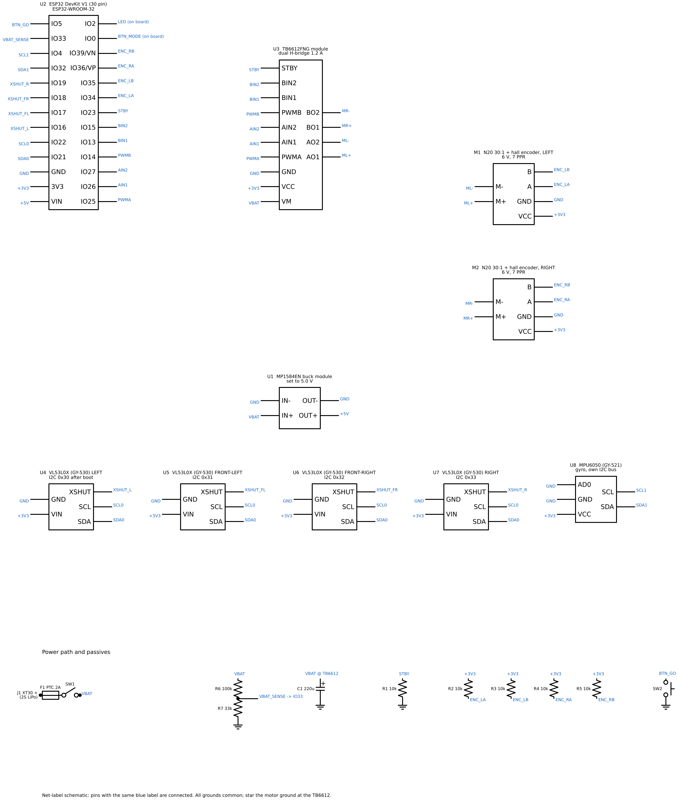
The schematic, the netlist (hardware/netlist.csv) and the firmware pin map come from one script, hardware/schematic.py, which fails CI if a pin in firmware/include/config.h disagrees with the drawing. The full bill of materials (about 80 to 120 USD with spares) and the wiring table are in hardware/README.md.
Key numbers
| Quantity | Value | Consequence |
|---|---|---|
| Body | 95 × 80 mm, axle at the centre | pivot circle 124 mm in a 168 mm corridor; limits the radius of the turns that pass close to a post (F45, V90b, D135b) |
| Wheel | 32 mm diameter, 840 counts per turn | 0.12 mm per count: one count per 1 ms tick is 0.12 m/s of speed noise, hence the filtered D term |
| Motor model | k = 0.0019 V s/rad at the shaft, R = 10 Ω, 30:1 at 70 % | top speed 2.1 m/s at 7.6 V, stall acceleration 29 m/s² |
| Traction | mu = 0.7 nominal | 6.9 m/s²: the robot is traction limited, which sets every acceleration in the presets |
| Mass, inertia | 130 g, 1.6e-4 kg m² | radius of gyration 35 mm: grip allows 83 to 163 rad/s² of yaw acceleration at 4 m/s² lateral (\(\mu\) = 0.5 to 0.7), the limit that caps the turns |
The derivations behind each line are in the engineering notebook.
Rules that prevent the classic failures
- Encoders on 3.3 V. GPIO34 to GPIO39 are not 5 V tolerant.
- Set the buck to 5.0 V with a meter before connecting the ESP32. These modules often ship at 12 V.
- Star ground. Motor return current goes straight to the battery, not through the logic ground.
- Twist motor wires and put 100 nF across each motor's terminals.
- IMU near the axle centre, rigidly mounted: vibration becomes gyro noise, an off-centre IMU sees centripetal acceleration.
- Strapping pins (IO0, IO2, IO5, IO12, IO15) only where their boot state is harmless.
What Mk I cannot do
The studies point at four limits of this hardware, and each one is a line item of the Mk II proposal:
- 30 Hz wall sensing. At 1.2 m/s the robot moves 40 mm between ToF samples.
- A layout that ignores yaw inertia. Turn speed is capped by angular acceleration, and the grip limit on it falls with the square of the radius of gyration; the wide body also costs the turns that pass close to a post up to 22 % of their speed.
- A consumer gyro whose scale (±3 %) and temperature drift decide whether diagonal runs survive.
- No motor current measurement, so traction loss can only be inferred from tracking error.